Control Solenoid Valve and Transmission Control Module Assembly Input Shaft Speed/Output Shaft Speed Input Test
Special Tools
* DT-47825-10 - Jumper Harness
* J 35616 - GM-Approved Terminal Test Kit
* J 38522 - Variable Signal Generator
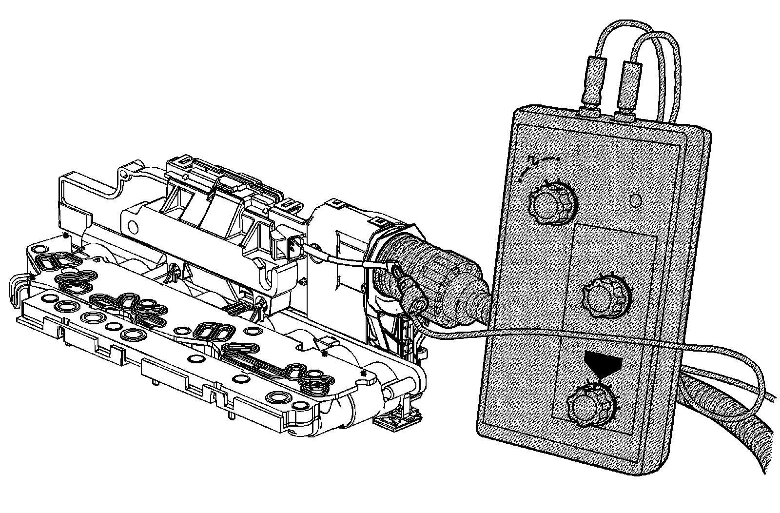
The purpose of this test is to provide a simulated input/output speed sensor (ISS/OSS) signal to the control solenoid valve assembly ISS/OSS input circuits.
Transmission Input Speed Sensor
1. Ignition OFF, connect the DT-47825-10 - jumper harness between the vehicle wire harness electrical connector, and the control solenoid valve assembly electrical connector.
2. Disconnect the ISS/OSS wiring harness connector X3 (1) from the control solenoid valve assembly.
3. Ignition ON, test for 8.3-9.3 volts between the ISS/OSS voltage circuit terminal B on the control solenoid valve assembly and ground at the transmission case.
• If not within the specified range, replace the control solenoid valve assembly. Refer to Control Solenoid Valve and Transmission Control Module Assembly Replacement Service and Repair.
4. Using the J 35616 - terminal test kit, connect the J 38522 - variable signal generator red lead to the ISS signal circuit terminal A on the TCM.
5. Connect the black lead from the J 38522 - variable signal generator to ground at the transmission case.
6. Set the J 38522 - variable signal generator to 5 volts, the frequency to 300, and the percent duty cycle to 50 or the normal position.
7. Ignition ON, verify with a scan tool the Transmission ISS parameter is between 760-785 RPM.
• If not within the specified range, replace the control solenoid valve assembly. Refer to Control Solenoid Valve and Transmission Control Module Assembly Replacement Service and Repair.
Transmission Output Speed Sensor
1. Ignition OFF, connect the DT-47825-10 - jumper harness between the vehicle wire harness electrical connector, and the control solenoid valve assembly electrical connector.
2. Disconnect the ISS/OSS wiring harness connector X3 (1) from the control solenoid valve assembly.
3. Ignition ON, test for 8.3-9.3 volts between the ISS/OSS voltage circuit terminal B on the control solenoid valve assembly and ground at the transmission case.
• If not within the specified range, replace the control solenoid valve assembly. Refer to Control Solenoid Valve and Transmission Control Module Assembly Replacement Service and Repair.
4. Using the J 35616 - terminal test kit, connect the J 38522 - variable signal generator red lead to the OSS signal circuit terminal C on the TCM.
5. Connect the black lead from the J 38522 - variable signal generator to ground at the transmission case.
6. Set the J 38522 - variable signal generator to 5 volts, the frequency to 300, and the percent duty cycle to 50 or the normal position.
7. Ignition ON, verify with a scan tool the Transmission OSS parameter is between 495-505 RPM.
• If not within the specified range, replace the control solenoid valve assembly. Refer to Control Solenoid Valve and Transmission Control Module Assembly Replacement Service and Repair.