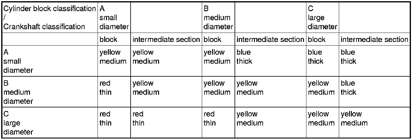
Classification of Main Bearings
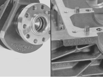
The marking is stamped on the cylinder block and crankshaft.
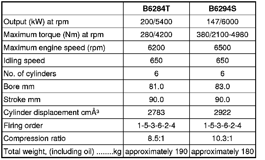
General Data
Cylinder Block
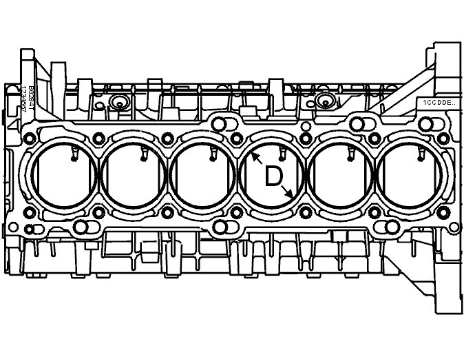
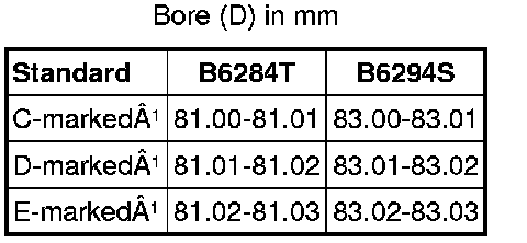
(1)The bore classification is stamped on top of the engine block.
Example: 1CCDDEE Is read as follows: Cylinder 1=C; Cylinder 2=C; Cylinder 3=D; Cylinder 4=D; Cylinder 5 =E; Cylinder 6=E.
Intermediate Section
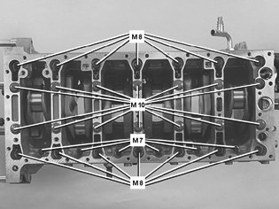
Replace M10 screws
Tighten screws in sequence from center and outwards
First pass: M10 20 Nm
Second pass: M10 45 Nm
Third pass: M8 24 Nm
Fourth pass: M7 17 Nm
Final pass: M10 90°
Connecting Rod Fasteners
First pass 20 Nm
Final pass Tighten 90°
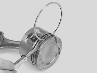
Pistons
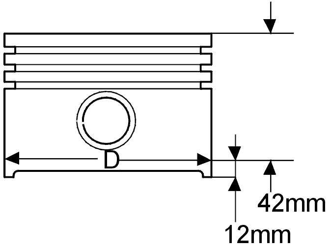
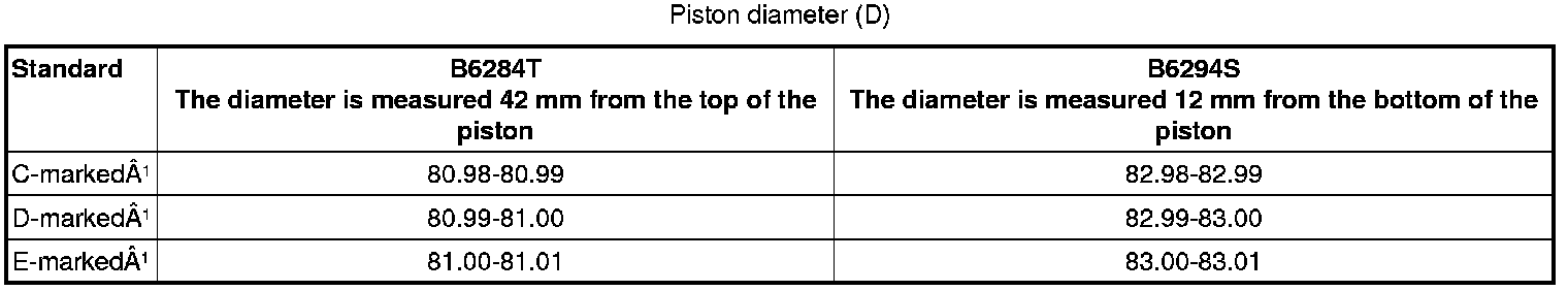
(1)The classification is marked on the top of the piston.
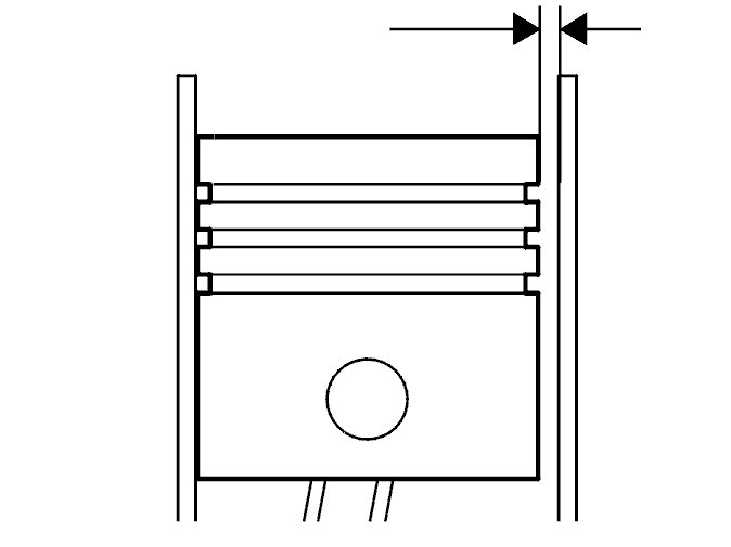
Piston Rings
Upper compression ring 0.030-0.070 mm
Lower compression ring 0.030-0.070 mm
Oil control ring assembly 0.038-0.142 mm
Upper 1.200 -0.010/-0.030 mm
Lower 1.500 -0.010/-0.030 mm
Spring 1.510 ± 0.020 mm
Rail 0.460 ± 0.011 mm
B6284T
Diameter 23.000 ± 0.004 mm
Length 61.000 ± 0.200 mm
B6294S
Diameter 21.000 ± 0.004 mm
Length 57.000 ± 0.200 mm
Classification Marking
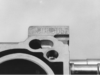
Each cylinder is stamped with a classification letter (C, D or E) at the rear edge of the cylinder block.
Crankshaft Center Nut 300 Nm (221 ft.lb)
Vibration Damper Screws
Install new screws
First pass 35 Nm (26 ft.lb)
Final pass Tighten 50°