TE MFI#7
MFI#7 No mass air flow (MAF) signal
Fault Message Conditions:
The fault message is logged when voltage is below 1 V.
Causes of fault:
Break or grounding in the wiring between MFI#7 and the MAF sensor.
Break or grounding in the MAF sensor.
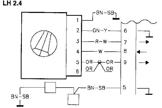
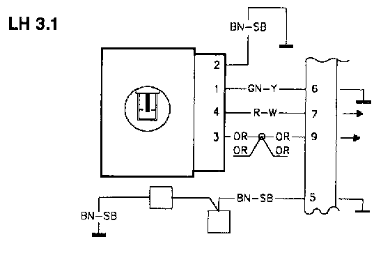
Break to power supply terminal 5 (LH 2.4) or 3 (LH 3.1) on the MAF sensor.
Fault symptoms:
The engine runs rough. Uneven idling.
TE1
Volvo ST, Test Box
-Disconnect the ST in accordance with QA2. Connecting The Volvo Scan Tool (ST)
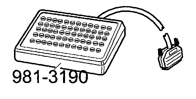
-Connect the test box to MFI and check GND points in accordance with P1-P2.
-Continue with Checking the MAF sensor and the wiring resistance TE2.
TE2
Checking The Mass Air Flow (MAF) Sensor And The Wiring Resistance
-Ignition off.
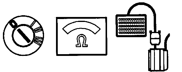
Connect an ohmmeter between MFI LH #7 and MFI LH #5 GND.
LH 2.4: The ohmmeter should read approx. 4 OHMS.
LH 3.1: The ohmmeter should read just over 110 OHMS.
If this value Is OK:
-Check the resistance to ground (GND) TE3. it the reading is incorrect:
-Check the wiring between MFI#7 and the MAF sensor for breaks in accordance with NA2. Checking the Wiring
TE3
Checking The Resistance To GND
-Ignition off.
-Disconnect the MAF sensor.
Connect an ohmmeter between MFI#7 and MFI#5 (GND). The ohmmeter should read infinite resistance.
If this value is OK
-Check the power supply TE4
If the reading is incorrect
-Check the wiring between MFI#7 and the MAF sensor for grounding.
TE4
Checking The Power Supply
-Connect the control module to the test box and the MAF sensor.
-Re-install system fuse.
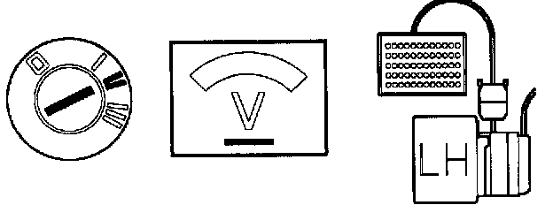
-Ignition on.
LH 2.4: Connect a voltmeter between terminal 5 on the MAF sensor and GND.
LH 3.1: Connect a voltmeter between terminal 3 on the MAF sensor and GND.
The voltmeter should read battery voltage.
If this value is OK:
-Check the MAF sensor TE5.
If the reading is incorrect:
-Check the wiring between terminal 5 (LH 3.1: terminal 3) and the [1][2]system relay for breaks in accordance with NA2. Checking the Wiring
TE5
Checking The Mass Air Flow (MAF) Sensor
-Connect the MAF sensor.
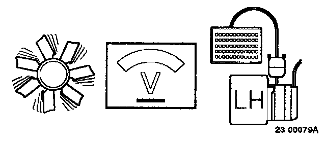
-Start and warm up the engine.
LH 2.4: Connect a voltmeter between MFI LH #7 and MFI LH #5 (GND).
-Take readings when the engine is unloaded and idling.
LH 2.4: The voltmeter should read approx. 2.3 V.
LH 3.1: The voltmeter should read approx. 3.5 V.
If this value is OK:
Intermittent fault
-Check the wiring between MFI#7 and the MAF sensor for loose contacts.
-Check the wiring between terminal 5 (LH 3.1: terminal 3) and the [1][2]system relay for loose contacts.
If the reading is incorrect:
-Try using a new MAF sensor.