TB. MFI#2 I DI#7 (MFI LH 2.4)
MFI#2 / DI#7 Idle switch status varies
Fault Message Conditions:
If both MFI and ICM are connected the fault message will be logged if the voltage at the terminals is different is not over or under 1.2 V. at the same time.
Fault Causes:
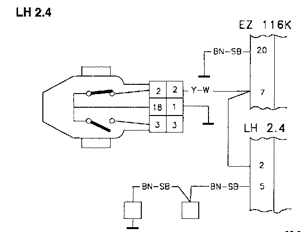
Break in the wiring between the TP switch and MFI#2. Break in the wiring between the TP switch and DI#7.
Fault Symptoms:
Wrong idle speed.
No fuel shut-off when the engine is braking the car.
NOTE: When checking wiring, the ST should be disconnected.
TB1
Monitor Test
-Start the engine without touching the AP.
-Check to see if IDLING is displayed in Monitor Test.
If IDLING Is Displayed:
-Volvo ST, Test box TB2.
If IDLING is not displayed:
-Check the wiring between MFI#2 and the TP switch for breaks in accordance with NA2. Checking the Wiring
TB2
Volvo ST, Test Box
-Disconnect the ST in accordance with CA2. Connecting The Volvo Scan Tool (ST)
-Connect the test box to DI and check the GND points.
-Continue with Checking idling signal to DI SB3.
TB3
Checking Idling Signal To DI
-Connect the DI control module to the test box.
-Install the fuse.
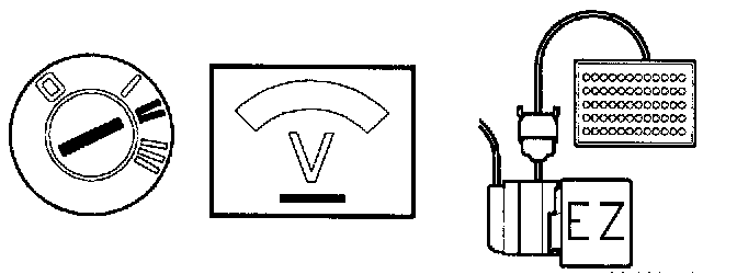
-Ignition on.
Connect a voltmeter between DI#7 and DI#20. The voltmeter should read approx. 0 V.
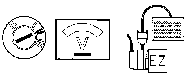
-Turn the throttle pulley so that the idle switch opens. The voltmeter should read approx. 12 V.
If this reading is OK:
-Check the connections between DI#7 and the TP switch for loose contacts.
-Check the connections between MFI#2 and the TP switch for loose contacts.
If the reading is incorrect:
-Check the wiring between DI#7 and the TP switch for breaks in accordance with NA2. Checking the Wiring