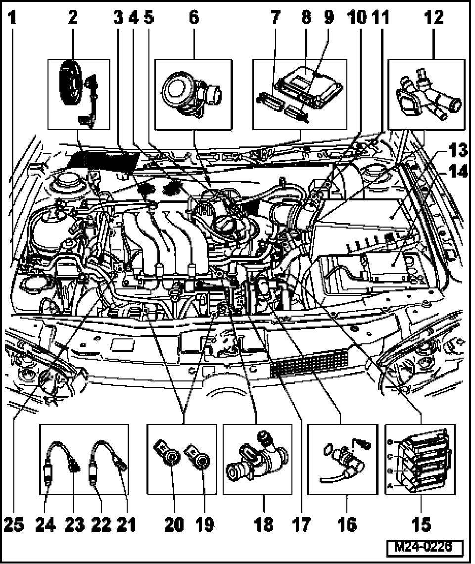
Overview of Component Locations (Vehicles with engine code AVH, AZG)
The following components are not displayed in the installation overview:
- Malfunction Indicator Lamp (MIL) -K83-*
- Electronic Power Control (EPC) Warning Lamp -K132-*
- Leak Detection Pump (LDP) -V144-*
- Under wheel housing liner in rear right wheel housing
- Throttle Position (TP) sensor -G79-*
- Clutch vacuum vent valve switch -F36-*
- Component location: in left footwell
The following components are displayed in the Component location overview:
1 Evaporative Emission (EVAP) Canister Purge Regulator Valve -N80-*
- Installation position: Arrow points in direction of flow
2 Camshaft Position (CMP) sensor -G40-*
- Terminals of sensor and connector are gold-plated
3 Intake manifold
4 Throttle valve control module-J338-*
5 Positive Crankcase Ventilation (PCV) heating element -N79-
6 Combination valve
7 Connector, 81-pin
- for Engine Control Module (ECM)
- Switch ignition off before disconnecting or connecting connector
- disengage to pull off
8 Engine Control Module (ECM)*
- Component location: in plenum chamber
9 Connector, 40-pin
- for Engine Control Module (ECM)
- Switch ignition off before disconnecting or connecting connector
- disengage to pull off
10 Mass Air Flow (MAF) sensor -G70-* with Intake Air Temperature (IAT) sensor (G42)*
11 Protective housing for relay
- Relay position assignment in protective housing, see Fig. 1
12 Engine Coolant Temperature (ECT) sensor -G62-*
- for Engine Control Module (ECM)
- with Engine Coolant Temperature (ECT) Sensor -G2-
- If necessary, release pressure in cooling system before removing
13 Air filter housing
14 Protective housing
- For additional fuses
15 Ignition coil with power output stage (-N70-, -N127-, -N291-, -N292-)*
16 Engine speed sensor (G28)*
- Tightening torque: 10 Nm
17 Secondary Air Injection (AIR) pump motor -V101-*
18 Fuel injectors (-N30- through -N33-)*
19 Knock Sensor (KS) 2 -G66-*
- Terminals of sensor and connector are gold-plated
20 Knock Sensor (KS) 1 -G61-*
- Terminals of sensor and connector are gold-plated
21 4-pin harness connector
- brown
- Terminals 3 and 4 gold-plated
- For Heated Oxygen Sensor (HO2S) 2 behind Three Way Catalytic Converter (TWC) -G130- and Oxygen Sensor (O2S) Heater 1 (behind Three Way Catalytic Converter (TWC)) -Z29-
- Component location: At right vehicle underside
22 Oxygen Sensor (O2S) Behind Three Way Catalytic Converter (TWC) -G130- bank 1*, 50 Nm
- Component location: In rear catalytic converter
- Only use "G 052 112 A3" to grease thread; do not let "G 052 112 A3" get onto slit of oxygen sensor
- Voltage supply of oxygen sensor heater via Fuel Pump (FP) Relay -J17-
23 6-pin harness connector
- Terminals are gold-plated
- Black, 6-pin
- For Heated Oxygen Sensor (HO2S) 1 before Three Way Catalytic Converter (TWC) -G39- and Oxygen Sensor (O2S) heater -Z19-
- Component location: At right vehicle underside
24 Heated Oxygen Sensor (HO2S) -G39- bank 1*, 50 Nm
- Component location: In exhaust manifold
- Use "G5" to grease thread only; do not let "G5" get onto slits of oxygen sensor body
- Voltage supply of oxygen sensor heater via Fuel Pump (FP) Relay -J17-
25 Fuel pressure regulator
Fig. 1 Relay position assignment in protective housing (engine compartment, left)
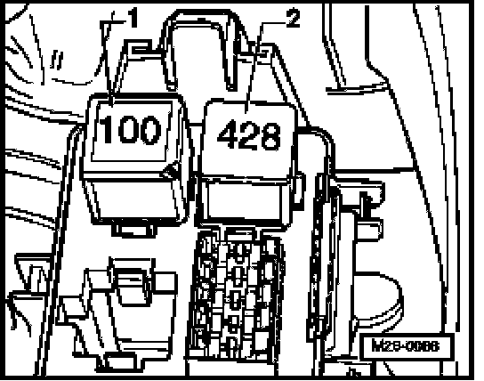
1 Secondary Air Injection (AIR) Pump Relay -J299-*
2 Motronic Engine Control Module (ECM) voltage supply relay -J271-*
NOTE:
- Remove battery Ground (GND) strap if tools are necessary for removal of relays or control modules from the relay carrier.
- Obtain radio code for radios with anti-theft coding before disconnecting battery.
- Check relay activation.