Throttle Valve Control Module, Checking
Components of throttle valve control module (J338):Throttle valve drive (G186), angle sensor 1 for throttle valve drive (G187), and angle sensor 2 for throttle valve drive (G188).
NOTE: When the throttle valve control module is replaced, it is absolutely necessary to adapt the new control module to the Engine Control Module (ECM).
Special tools and equipment
- VAG1551 scan tool (or VAG1552 mobile scan tool) with VAG1551/3B cable
- VAG1598/31 test box
- VAG1526 multimeter or VAG1715 multimeter
- VAG1594 connector test kit
- Wiring diagram
Test requirements
- Throttle valve must not be damaged or dirty.
- For automatic transmission, selector lever must be in -P- or -N-.
- Coolant temperature must be at least 85 °C, See display group 04, display field 3
NOTE: Use only gold-plated terminals when servicing terminals in harness connector of throttle valve control module.
- Connect VAG1551 scan tool (VAG1552). Then switch ignition on and select the Engine Control Module (ECM) using address word 01.
Connecting scan tool and selecting ECM. Refer to " Scan Tool Testing/Scan Tool Connecting and Initial Checks " Testing and Inspection
Indicated on display:
Rapid data transfer HELP
Select function XX
- Press buttons -0- and -8- to select "Read measuring value block" function 08. Press -Q- button to confirm input.
Indicated on display:
Read measuring value block
Enter display group number XXX
- Press 0, 6 and 2 for the function "display group number 62", and then press Q to exit from input mode.
- Check throttle angle of angle sensor -1- for throttle drive (power accelerator actuation) -G187- at idle stop in display field 1.
Display Group 62:
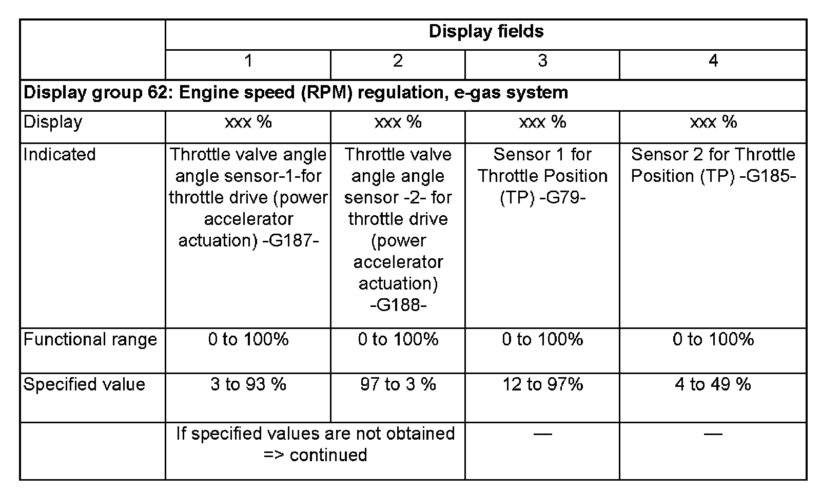
- Check throttle angle of angle sensor -1- for throttle drive (power accelerator actuation) -G188- at idle stop in display field 2.
- Press gas pedal slowly until it reaches Wide Open Throttle (WOT) position, and observe angle display in display fields 1 and 2:
Percent indication in display field 1 must rise uniformly. In the process, the tolerance range of 3 to 93% is not always used completely.
Percent indication in display field 2 must decrease uniformly. In the process, the tolerance range of 97 to 3% is not always used completely.
NOTE:
- The value indicated in display field 1 increases, but the value indicated in display field 2 decreases, because the potentiometers (angle sensors) in the throttle valve control module run in opposite directions.
- This means that the voltage tap of angle sensor 1 runs from 0 to 5 volts. (The more the throttle valve is opened, the larger the voltage; percent indication climbs).
- The voltage tap of angle sensor 2 runs from 5 to 0 volts. (The more the throttle valve is opened, the lower the voltage; the percentage decreases).
If specified values are obtained:
- Press the -> button.
- Press buttons -0- and -6- to select "End Output" function 06. Press -Q- button to confirm input.
- Switch ignition off.
Continuation
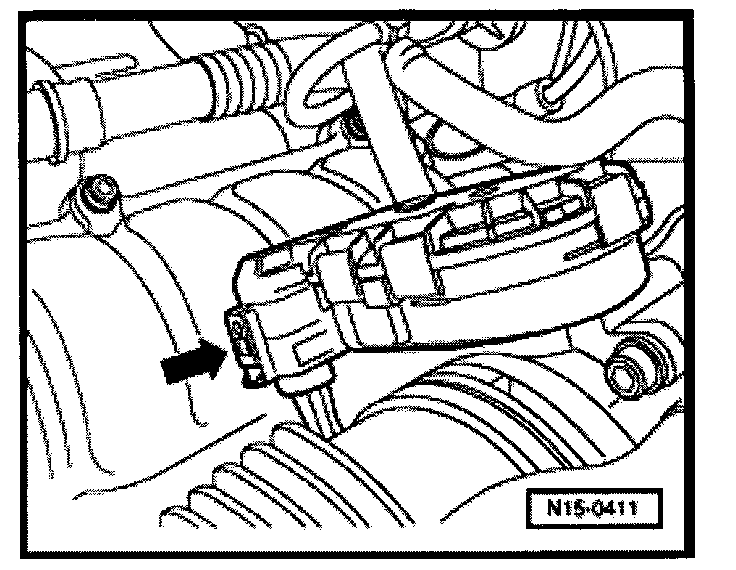
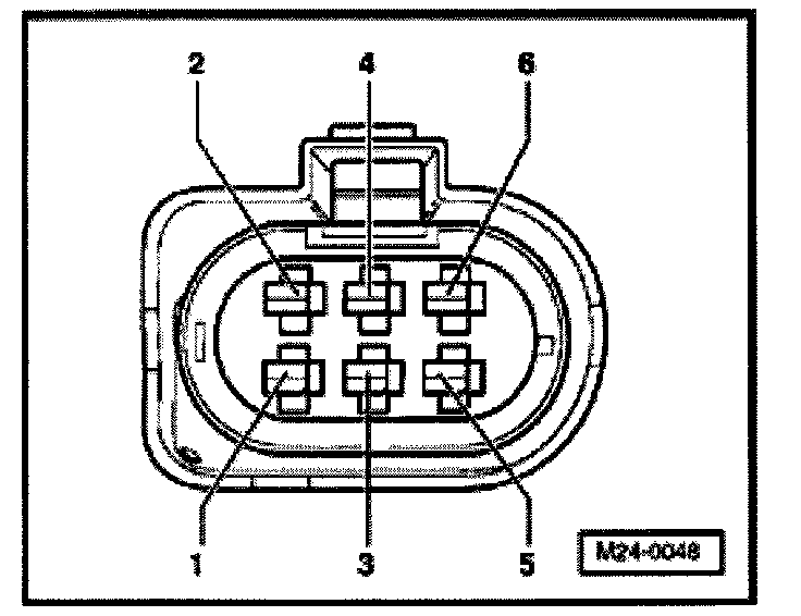
- Disconnect the 6-pin connector at the throttle valve control module (arrow).
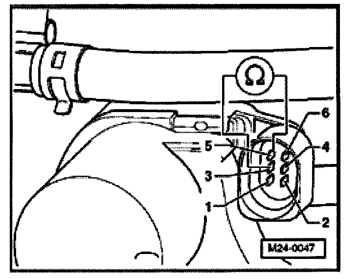
- Measure resistance of throttle valve drive between terminals 3 + 5 Specification: 1.0 to 5.0 Ohms
If specified value is not obtained:
- Replace throttle valve control module (J338).
- Check DTC memory, repair any malfunctions and then erase DTC memory.
- Adapt Engine Control Module (ECM) to throttle valve control module.
If specified value is obtained:
- Check voltage supply of throttle valve control module and wiring to control module.
- Check Throttle Position (TP) sensor and sensor 2 for accelerator pedal position:
If voltage supply and wires are OK:
- Replace Engine Control Module (ECM).
Checking voltage supply and wiring to control module

- Disconnect the 6-pin connector at the throttle valve control module (arrow).
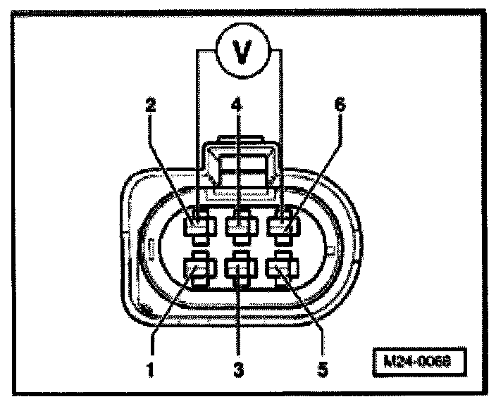
- Connect multimeter to terminal 2 + 6 of connector to make voltage measurement.
- Switch ignition on. Specification: at least 4.5 V
- Switch ignition off.
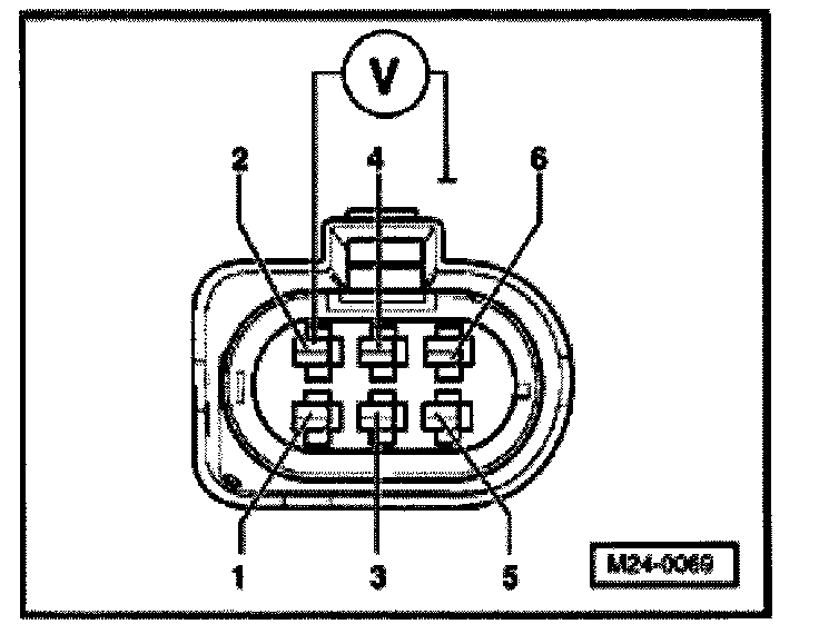
- Connect multimeter to terminal 2 of connector and Ground (GND) for voltage measurement.
- Switch ignition on. Specification: at least 4.5 V
- Switch ignition off.
If specified values are not obtained:
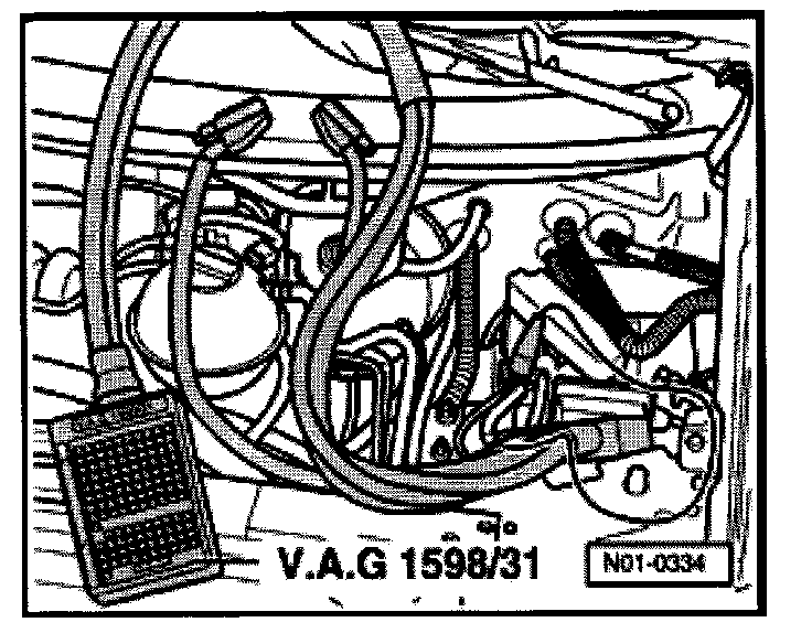
- Connect VAG1598/31 test box to control module wiring harness. Engine Control Module (ECM) is not connected.
- Check for open circuits in wires between test box and connector according to wiring diagram:
Terminal 1 + socket 92
Terminal 2 + socket 83
Terminal 3 + socket 117
Terminal 4 + socket 84
Terminal 5 + socket 118
Terminal 6 + socket 91
Wire resistance: max: 1.5 Ohms
- Also check wires for short circuit to each other. Specification: Infinity Ohms
- Also check wires for short circuits to B+ or Ground (GND). Specification: Infinity Ohms
If no malfunctions are found in wires:
- Check voltage supply of Engine Control Module (ECM). Testing and Inspection
After successful repair:
- Read readiness code. If DTC memory was erased or the Engine Control Module (ECM) was disconnected from the continuous B+ supply, the readiness code must be re-generated. Refer to Monitors, Trip and/or Drive Cycle (Readiness Codes)/Reading Readiness Code. Testing and Inspection Refer to Monitors, Trip and/or Drive Cycle (Readiness Codes)/Generating Readiness Code. Testing and Inspection