The Output Diagnostic Test Mode (DTM) actuates the following components in the sequence shown:
1. Fuel Injector, Cyl. 1 -N30-
2. Fuel Injector, Cyl. 2 -N31-
3. Fuel Injector, Cyl. 3 -N32-
4. Fuel Injector, Cyl. 4 -N33-
5. Fuel Injector, Cyl. 5 -N83-
6. Fuel Injector, Cyl. 6 -N84-
7. EVAP canister purge regulator valve -N80-
8. EGR vacuum regulator solenoid valve -N18-
9. Secondary Air Injection solenoid valve -N112-
10. Secondary Air Injection pump relay -J299-
11. Evaporative Emission (EVAP) canister purge solenoid valve -N115-
Special tools and equipment
- VAG 1551 Scan Tool with VAG 1551/3 adapter cable
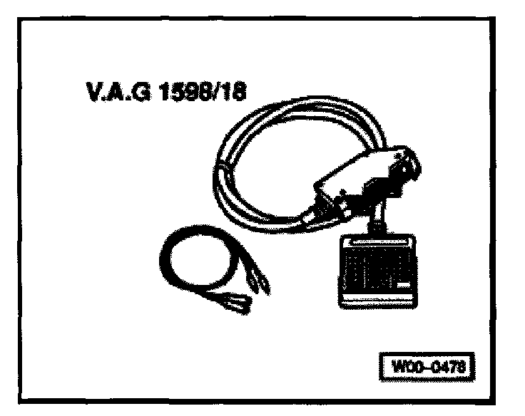
- VAG 1598/18 Test Box
- VAG 1527B LED Tester
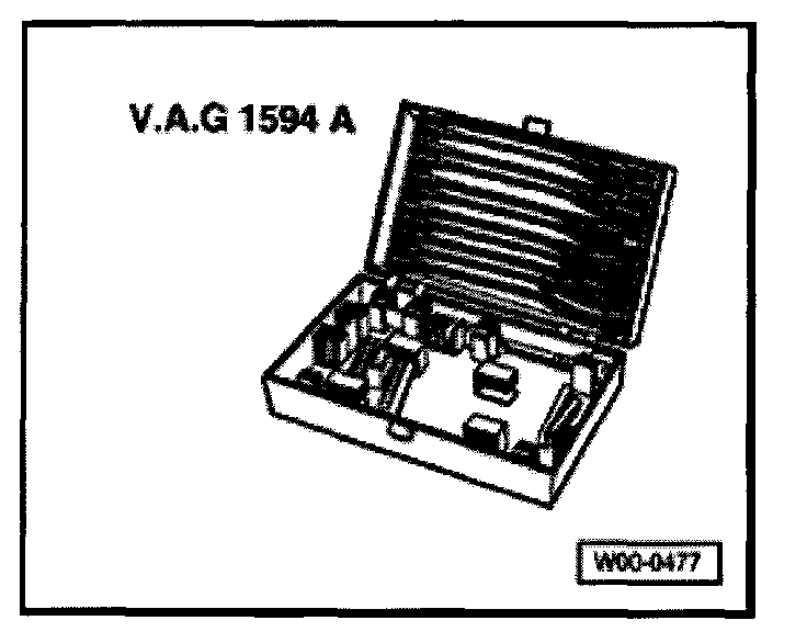
- VW 1594 Adapter kit
Test conditions
- Fuses 15, 18, S130 and S259 OK
- Throttle Position switch OK Testing and Inspection
NOTE:
- To activate the fuel injectors, the Throttle Position switch (in the Throttle Valve Control Module) must also be operated
- The output DTM can only be carried out if the engine is not running and the ignition switched on.
- The output DTM will be stopped if the engine is started or a rotational impulse is recognized.
- Components are checked audibly or by touch.
- If it is necessary to repeat the output DTM, without first running the engine, switch the ignition off for approx. 2 seconds.
Work sequence
- Connect VAG 1551/VAG 1552 Scan Tool.
- With ignition switched ON, press buttons -0- and -1- to select "Engine electronics" address word 01. [1][2][3][4]Reading and Clearing Diagnostic Trouble Codes
Display will appear as shown
Rapid data transfer HELP
Select Function XX
- Operate Scan Tool taking displayed information into account.
- Press buttons -0- and -3- to select "Output Diagnostic Test Mode" function 03.
Display will appear as shown
Rapid data transfer Q
03 - Output Diagnostic Test Mode
Cylinder 1 injector -N30- activating
- Press -Q- button to enter selection.
Display will appear as shown
Output Diagnostic Test Mode ->
Injector cylinder 1 -N30
- Open throttle to Wide Open position and then close completely
- Cyl. 1 injector must click several times
Cylinders 2 through 6 fuel injectors, individual activation
- Press -> button.
- Open throttle to Wide Open position and then close completely
- Cyl. 2 injector must click several times
To skip over an individual injector:
- Press -> button
If one or more injectors do NOT click:
- Proceed with output DTM until completed.
- Switch OFF ignition.
- Check fuel injector activation (resistance and amperage supply). Testing and Inspection
EVAP canister purge regulator valve -N80-, activating
- Press -> button.
Display will appear as shown
Output Diagnostic Test Mode ->
EVAP canister purge regulator valve -N80
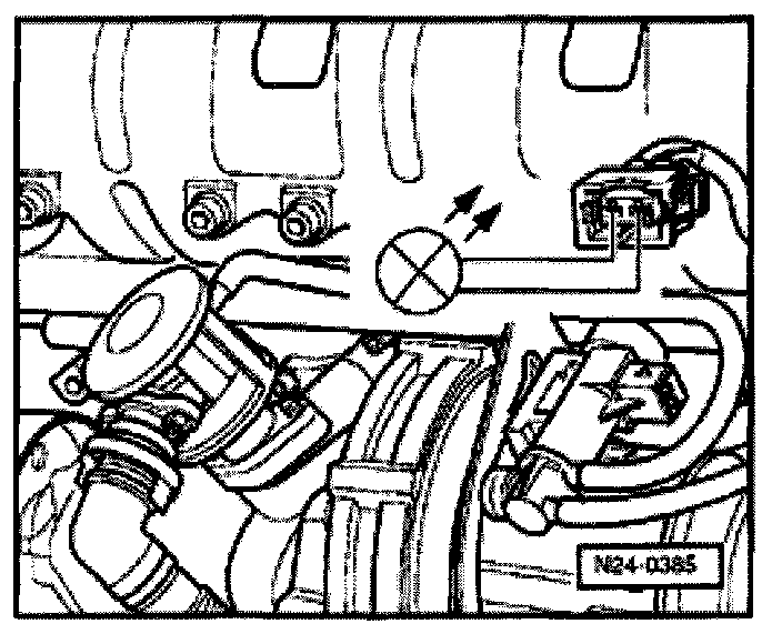
- EVAP canister purge regulator valve (mounted behind coolant expansion tank) must click until the next DTM component is selected by pressing -> button
- Disconnect EVAP canister at EVAP canister purge regulator valve.
- Attach piece of scrap hose to disconnected valve port.
- Blow into hose (in direction of Throttle Valve Control Module) during output DTM.
- Valve must open and close
If valve does not open and close:
- Disconnect 2-pin harness connector from -N80- valve and connect VAG 1527B LED tester to disconnected connector using jumper wires from VW 1594 adaptor kit.
- LED must flash
If LED flashes:
- Proceed with output DTM until completed and switch ignition off.
- Replace EVAP canister purge regulator valve -N80-.
If LED does not flash:
- Switch ignition off.
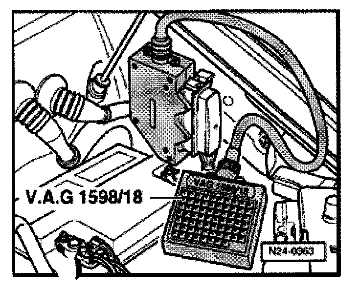
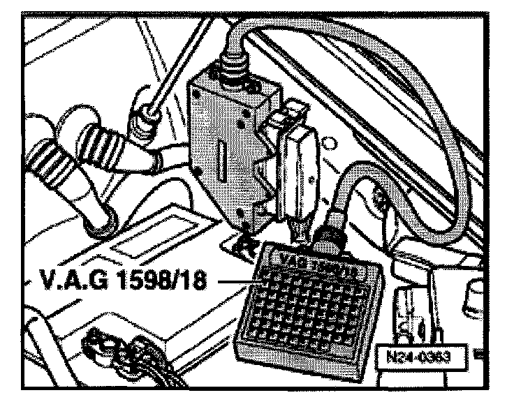
- Connect VAG 1598/18 Test Box to ECM harness connector.
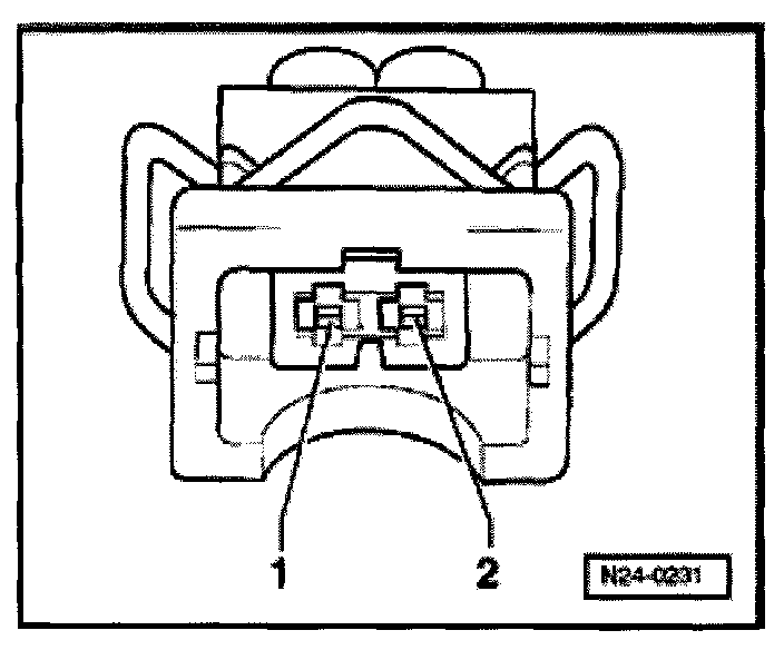
- Using wiring diagram, check for open circuit between Test Box socket 31 and terminal 1 of 2-pin harness connector.
- Resistance: 1.5 Ohms maximum
If wiring OK:
- Check -N80- voltage supply using wiring diagram, replace ECM -J220- if necessary.
EGR vacuum regulator solenoid valve -N18- activating
- Press -> button.
Display will appear as shown
Output Diagnostic Test Mode ->
EGR vacuum regulator solenoid valve -N18
- EGR valve must click until next DTM component is selected by pressing button
If EGR valve does not click:
- Disconnect 2-pin harness connector from -N18- valve and connect VAG 1527B LED tester to disconnected connector using jumper wires from VW 1594 adapter kit.
- LED must flash
If LED flashes:
- Replace EGR vacuum regulator solenoid valve
If LED does not flash:
- Switch ignition off.
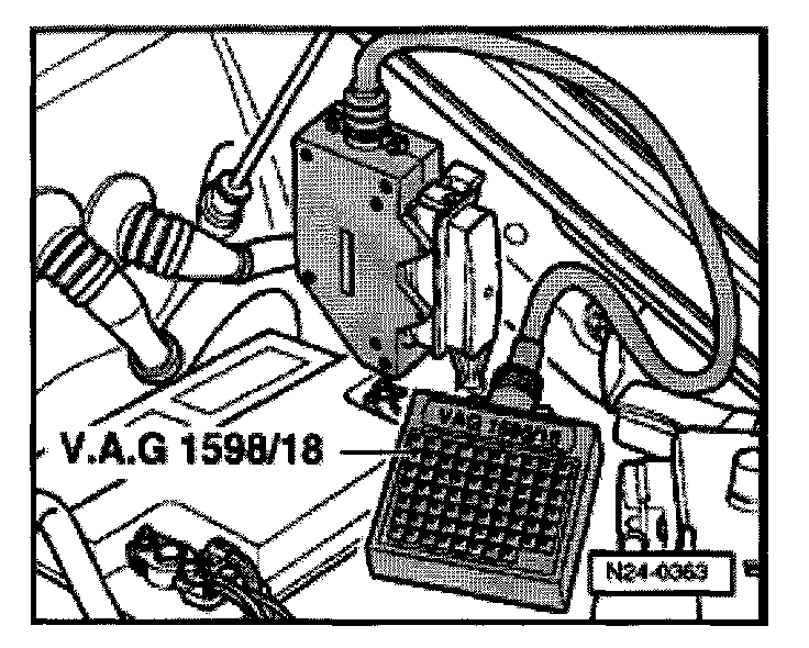
- Connect VAG 1598/18 Test Box to ECM harness connector.
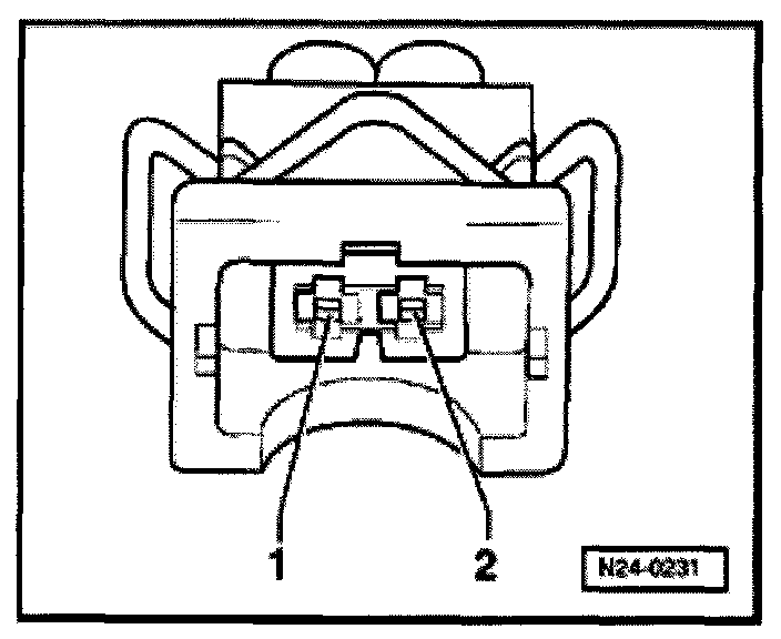
- Using wiring diagram, check for open circuit between Test Box socket 30 and terminal 2 of 2-pin harness connector
- Resistance: 1.5 Ohms maximum
If wiring OK:
- Check valve -N18- voltage supply using wiring diagram, replace ECM - J220- if necessary.
Secondary Air Injection solenoid valve -N112-, activating
- Press -> button.
Display will appear as shown
Output Diagnostic Test Mode ->
Secondary Air Injection solenoid valve N112
- Secondary Air Injection solenoid valve must click until next DTM component is activated by pressing -> button
If valve does not click:
- Disconnect 2-pin harness connector from -N112- valve and connect VAG 1527B LED tester to disconnected connector using jumper wires from VW 1594 adapter kit.
- LED must blink
- Replace Secondary Air Injection solenoid valve -N112-
If LED does NOT blink:
- Switch ignition off.
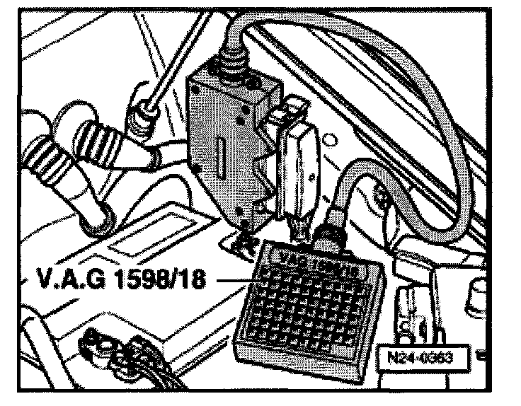
- Connect VAG 1598/18 Test Box to ECM harness connector.
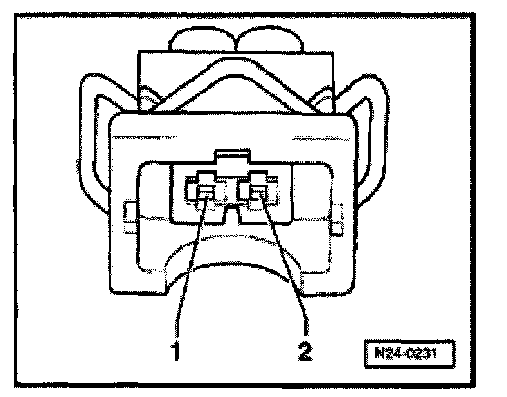
- Using wiring diagram, check for open circuit between Test Box socket 50 and terminal 1 of 2-pin harness connector.
Resistance: 1.5 Ohms maximum
If wiring OK:
- Check -N112- valve voltage supply using wiring diagram, replace -J220- ECM if necessary.
Secondary Air Injection pump relay -J299-, activating
- Press -> button.
Display will appear as shown
Output Diagnostic Test Mode ->
Secondary Air Injection pump relay -J299
The Secondary Air Injection pump relay -J299- activates the Secondary Air Injection pump motor -V101- which runs at intervals until the output DTM is terminated by pressing the -> button.
If motor does NOT run at intervals:
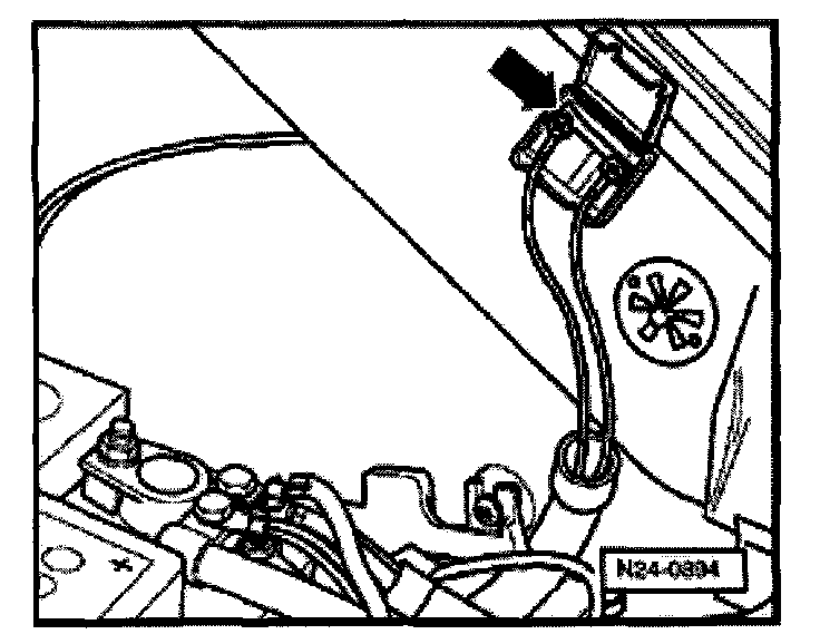
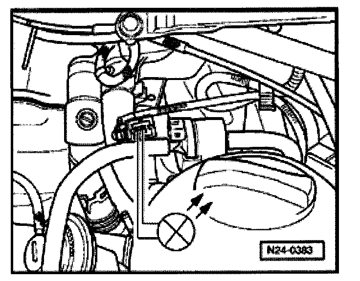
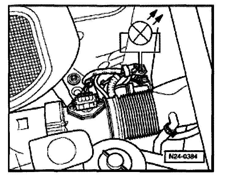
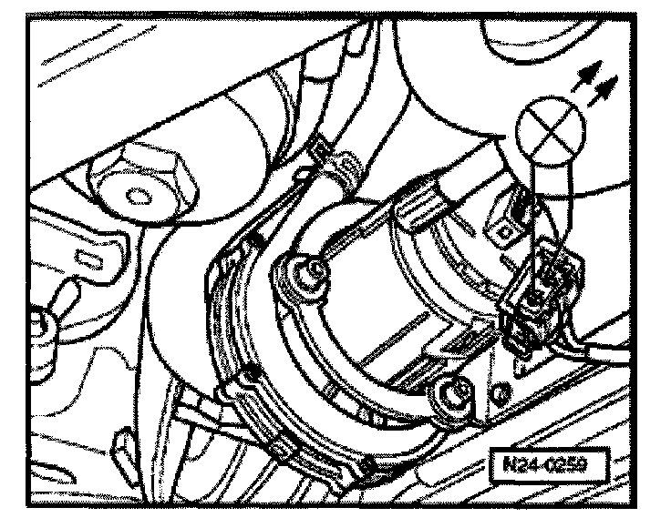
- Check fuse S130 (arrow) in left side of engine compartment.
If fuse is OK:
- Disconnect 2-pin harness connector from -V101- motor and connect VAG 1527B LED tester to disconnected connector using jumper wires from VW 1594 adapter kit.
- LED must blink
- Replace Secondary Air Injection pump motor -V101-.
If LED does not flash, but the secondary air injection pump relay clicks:
- Check wiring from secondary air pump to relay -J299- according to wiring diagram.
If LED does not flash and the secondary air injection pump relay does not click:
- Switch ignition off.
- Connect VAG 1598/18 Test Box to ECM harness connector.
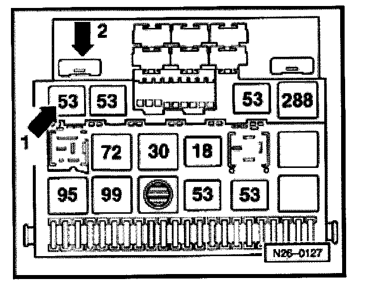
- Remove secondary air Injection pump relay (arrow 1) from fuse/relay panel
NOTE: If tools are required to remove relays or control modules from the fuse/relay panel; first disconnect the battery ground cable.
CAUTION!
Obtain the radio anti-theft code before disconnecting the battery ground cable!
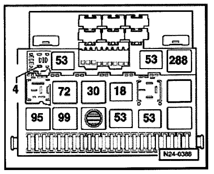
- Using wiring diagram, check for open circuit between Test Box socket 49 and terminal 4 of fuse/relay panel.
- Resistance: 1.5 Ohms maximum
If wiring OK:
- Check relay voltage supply according to wiring diagram. If necessary replace secondary air pump relay -J299-.
- If relay is not faulty, replace Motronic control module -J220-.
Evaporative Emission (EVAP) canister purge solenoid valve -N115-
- Press -> button.
Indicated on display
Output Diagnostic Test Mode ->
EVAP canister purge solenoid valve N115
The EVAP canister purger solenoid valve -N115- (located under the vehicle floor over the EVAP canister) clicks only one time when activated. The clicking noises that follow are transferred from the Leak Detection Pump. Pressing the -> button ends the output DTM.
Valve -N115- clicks but malfunction is still valid (leak diagnosis cannot be conducted):
- Check EVAP canister purge solenoid valve -N115-.
- Press -> button.
Display will appear as shown
Rapid data transfer HELP
Select Function XX
- Press buttons -0- and -6- to select "End output" function 06.
- Press -Q- button to enter selection.
NOTE: After completion of the Output Diagnostic Test Mode switch off the ignition. If the ignition is not switched off first, the engine will not start.