Oxygen Sensor and Oxygen Control (After Cat), Checking
Special tools and equipment
- VAG 1551/1552 Scan Tool using VAG 1551/3 adapter cable
- VAG 1598/18 Test Box
- Fluke 83 multimeter (or equivalent)
- VW 1594 Adapter kit
- Wiring diagram
Requirement
- Engine Coolant Temperature 80 °C minimum
Functional check
- Connect VAG 1551 (VAG 1552) Scan Tool Refer to Scan Tool Testing/VAG 1551 Scan Tool. Testing and Inspection
- With engine idling, press buttons -0- and -1- to select "Engine electronics" address word 01.
Display will appear as shown
Rapid data transfer HELP
Select function XX
- Press buttons -0- and -8- to select "Read measuring value block".
- Press -Q- button to enter selection.
Display will appear as shown
Read measuring value block HELP
Input display group number XXX
- Press buttons -1-, -1- and -6- to select "Display group number 116".
Display will appear as shown (1 to 4 = Display fields)
Read measuring value block 116 ->
1 2 3 4
- Note Oxygen sensor voltage (Display field 3).
Display Group 15:
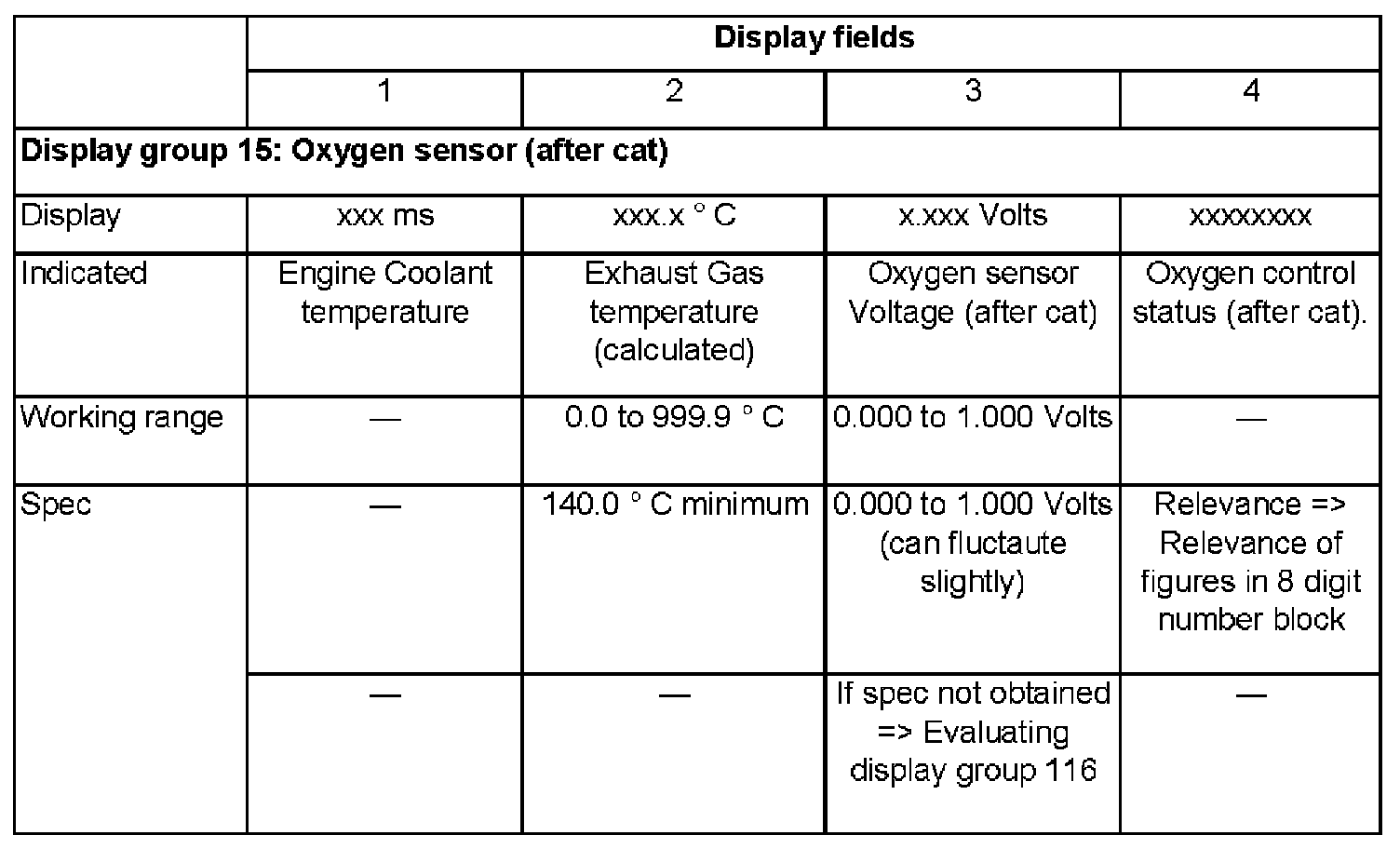
Continuation
- Road-test vehicle to remove possible build-up on oxygen sensor and repeat check.
If the specification in Display field 3 is not obtained even after road-testing:
- Check Oxygen sensor heating. Heater Check
- Raise engine speed above 3000 rpm.
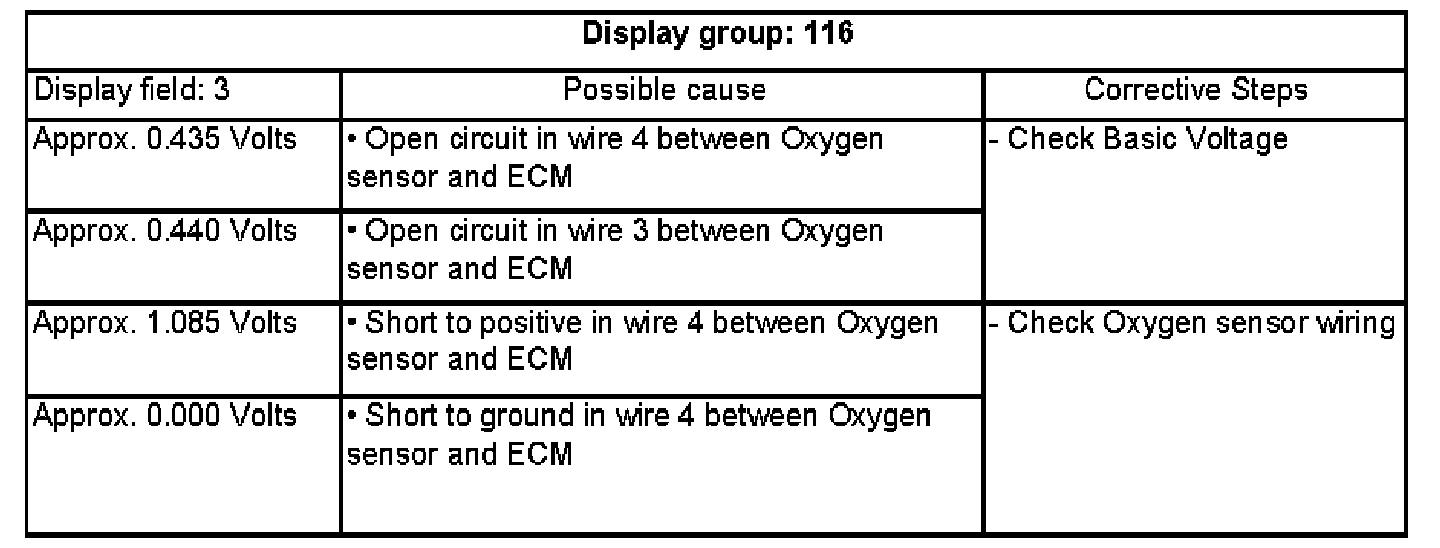
Evaluating display group 116
Display Group 116:
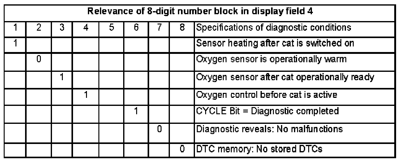
Relevance of figures in 8 digit number block
Basic Voltage, checking
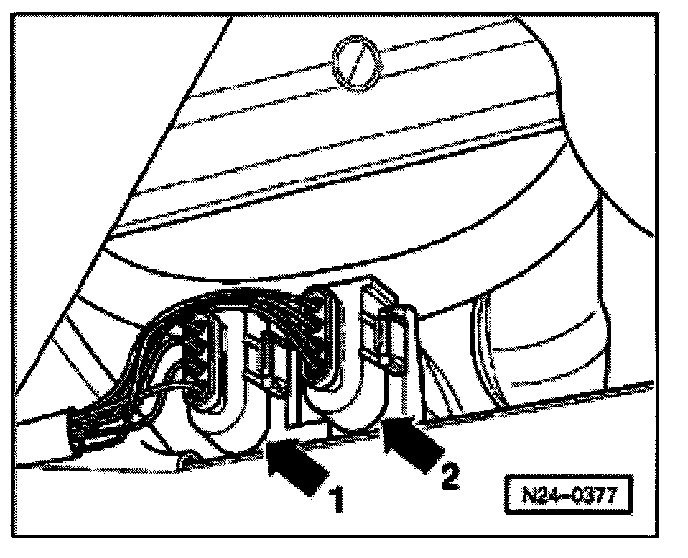
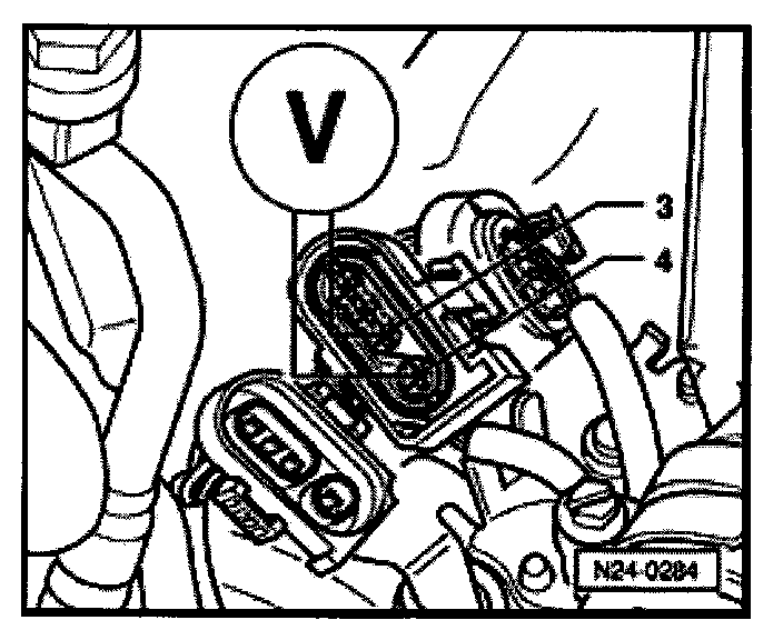
- Disconnect (brown) 4-pin connector to Oxygen sensor (after cat) -G108- -2-.
- Switch Fluke 83 multimeter to 2.0 Volt range.
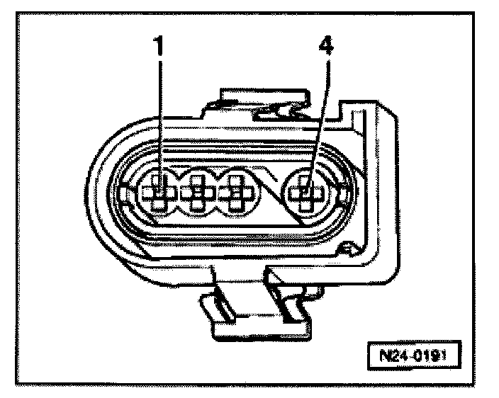
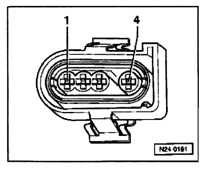
- Connect multimeter between terminals 3 + 4 of ECM connector using jumper wires from VW 1594 adapter kit.
- Start engine and measure Basic Voltage.
- specification: 0.40 to 0.50 Volts
- Switch ignition off.
If specification not obtained:
- Check oxygen sensor wiring
If specification obtained:
- Replace Oxygen sensor (after cat) -G108-.
Oxygen sensor wiring, checking
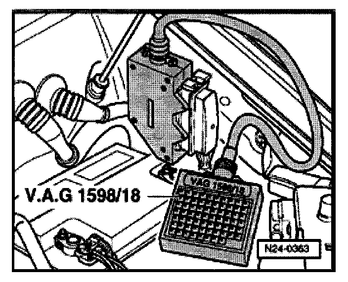
- Connect VAG 1598/18 Test Box to ECM wiring harness.

- Disconnect (brown) 4-pin connector to Oxygen sensor (after cat) -G108- -2-
- Check for open circuit between Test Box and 4-pin ECM connector using wiring diagram, connecting as follows:
terminal 3 + socket 58
terminal 4 + socket 13
- wire resistance: 1.5 Ohms maximum
- Check wires to 4-pin connector for shorting to one another.
terminal 4 + socket 58
- specification: infinity Ohms
- Check shielding for short to sensor wiring.
terminal 4 + socket 56
terminal 3 + socket 56
- specification: infinity Ohms
If wiring OK.
- Replace Engine Control Module -J220-.
- Perform Basic setting.
- Read-out Readiness code. Refer to Monitors, Trip and/or Drive Cycle (Readiness Codes)/Readiness Code Checking. Testing and Inspection
If DTC memory was erased:
- Create Readiness code. Refer to Monitors, Trip and/or Drive Cycle (Readiness Codes)/Readiness Code Generating Testing and Inspection