1 of 2
2 of 2
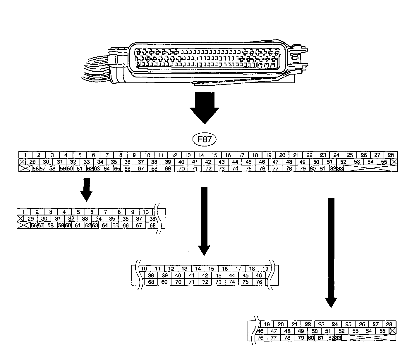
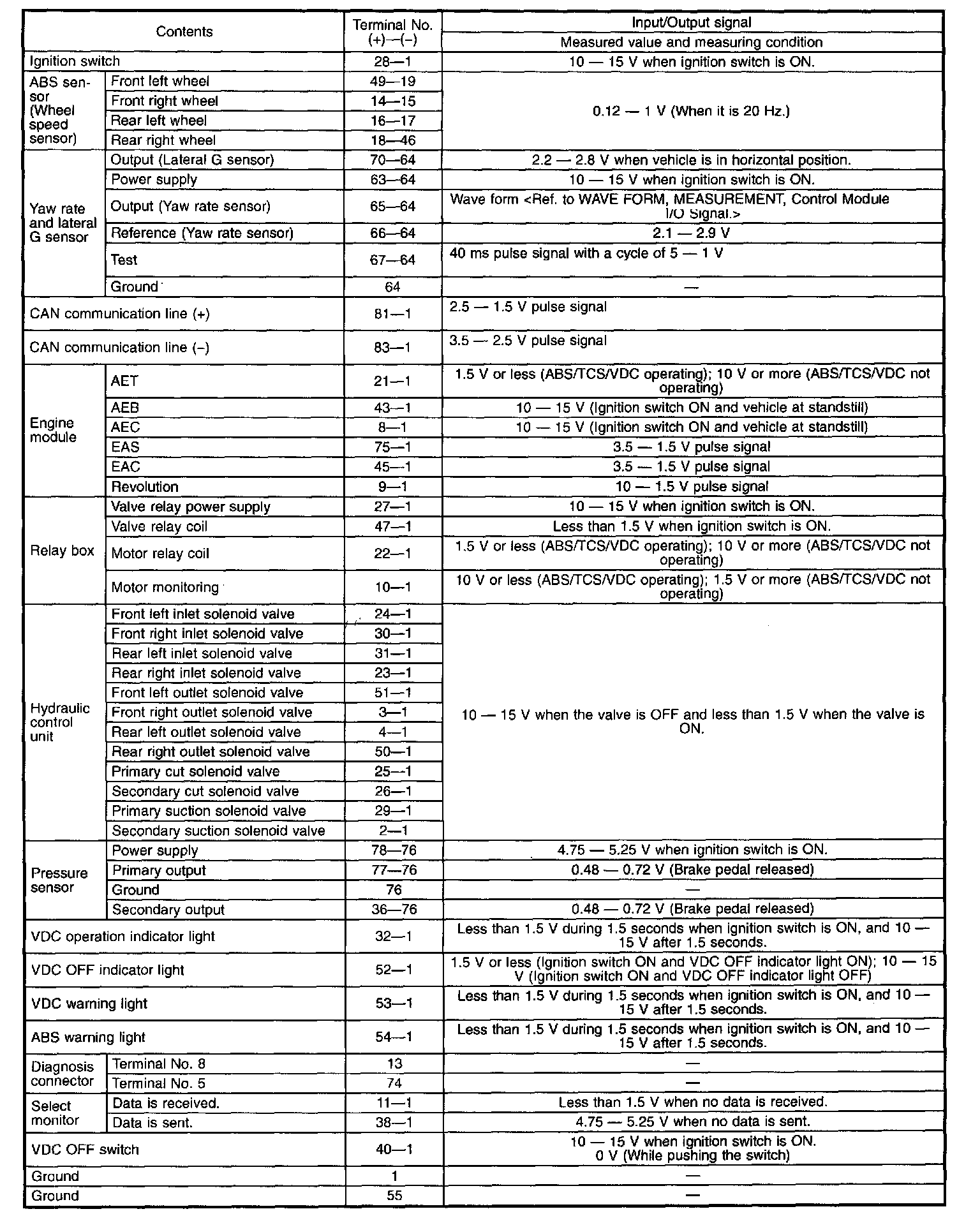
ELECTRICAL SPECIFICATION
NOTE:
^ The terminal numbers in the VDC control module connector are as shown in the figure.
^ When the connector is removed from the VDCCM, the connector switch closes the circuit between terminal No. 53, No. 54 and No. 55. The ABS and VDC warning light illuminate.
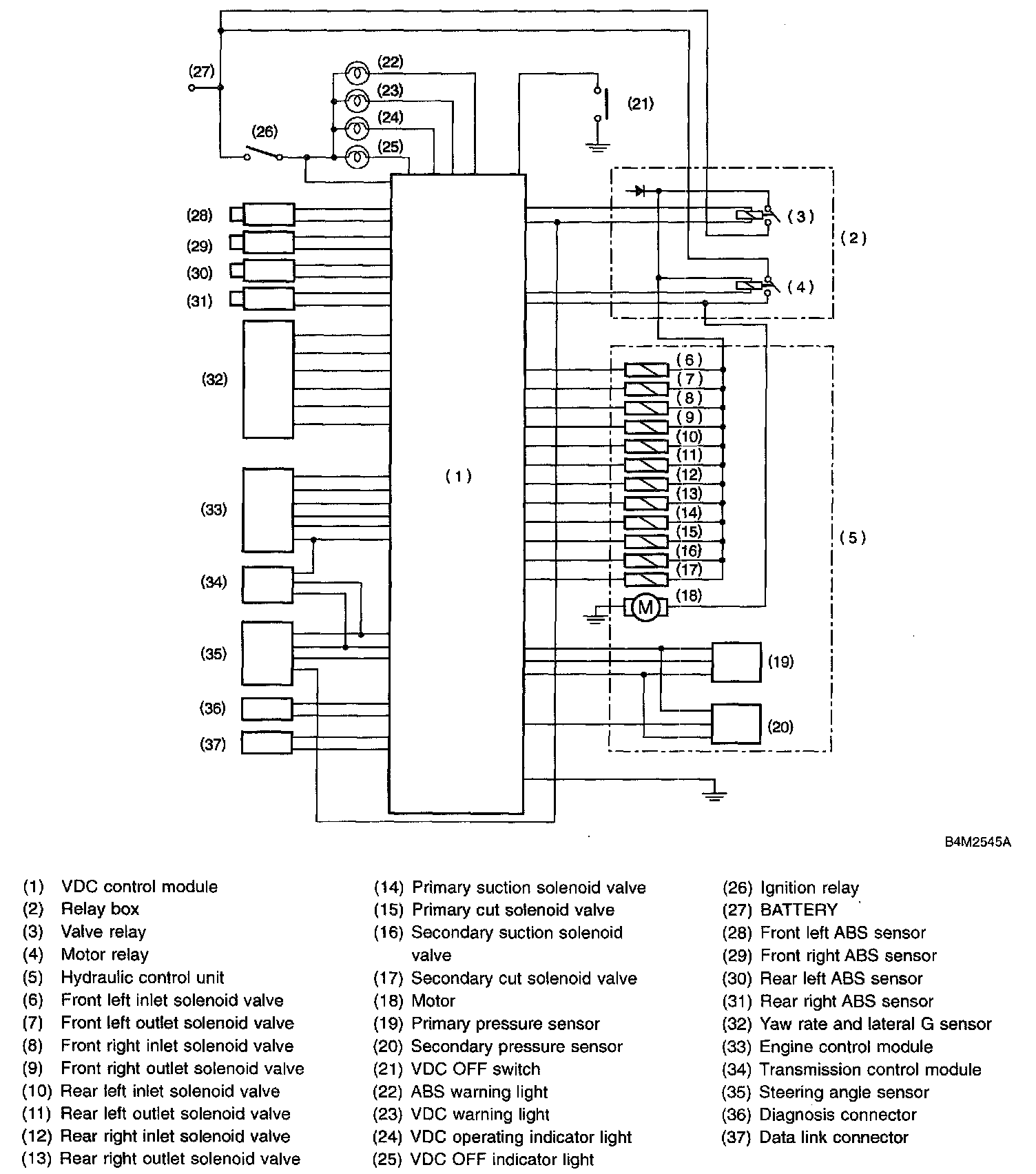
SCHEMATIC
MEASUREMENT
Measure input/output signal voltage.
NOTE: Measure with the VDCCM connector cover removed.
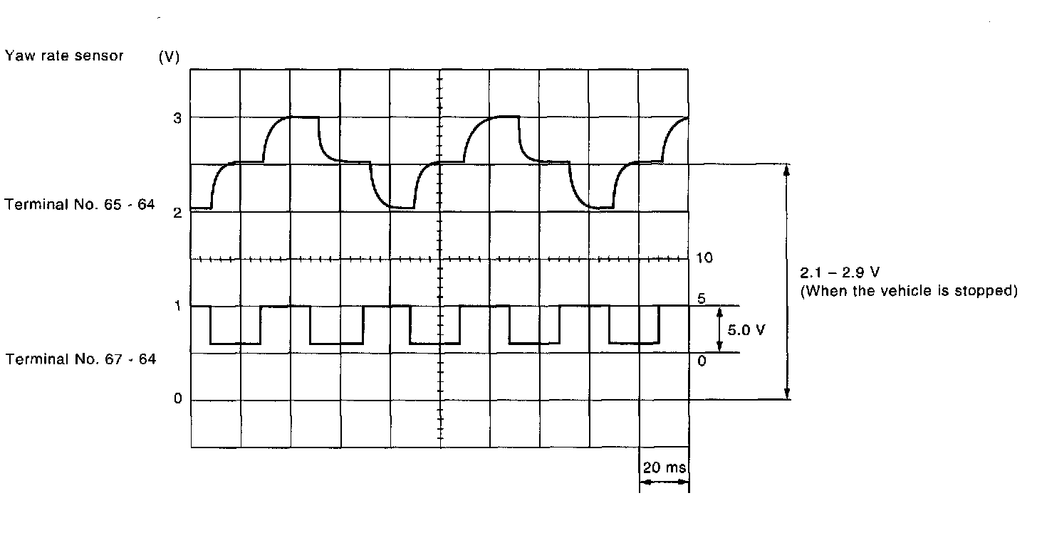
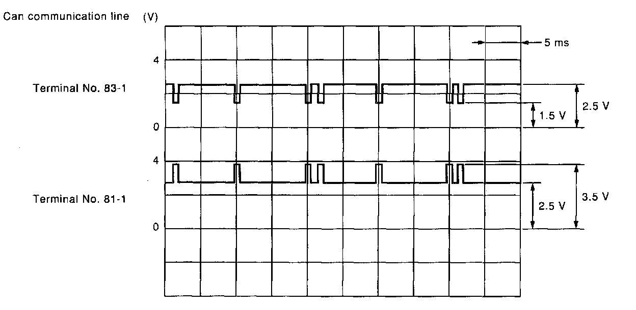
1. WAVE FORM
1 of 2
2 of 2