Scope
The following pages contain specified values and directions for measuring signals and levels on the automatic transmission control module.
Points to remember:
^ Observe the test conditions, use your common sense when judging the readings obtained.
^ The specified values are with the ignition in position ON unless stated otherwise.
^ First check that the control module is supplied with current and grounded.
^ Then check all sensor inputs and signals from other systems.
^ Finally, check the control module inputs. Remember that the test readings do not indicate whether or not the actuator is in working order.
^ If any reading is not OK, consult the wiring diagram to trace the leads, connectors or components which ought to be checked more thoroughly.
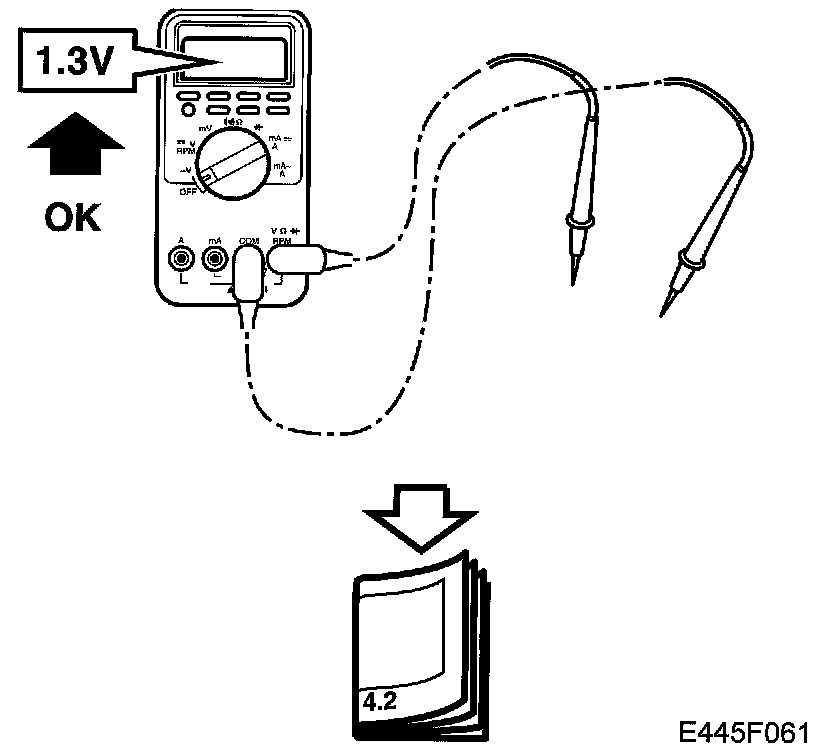
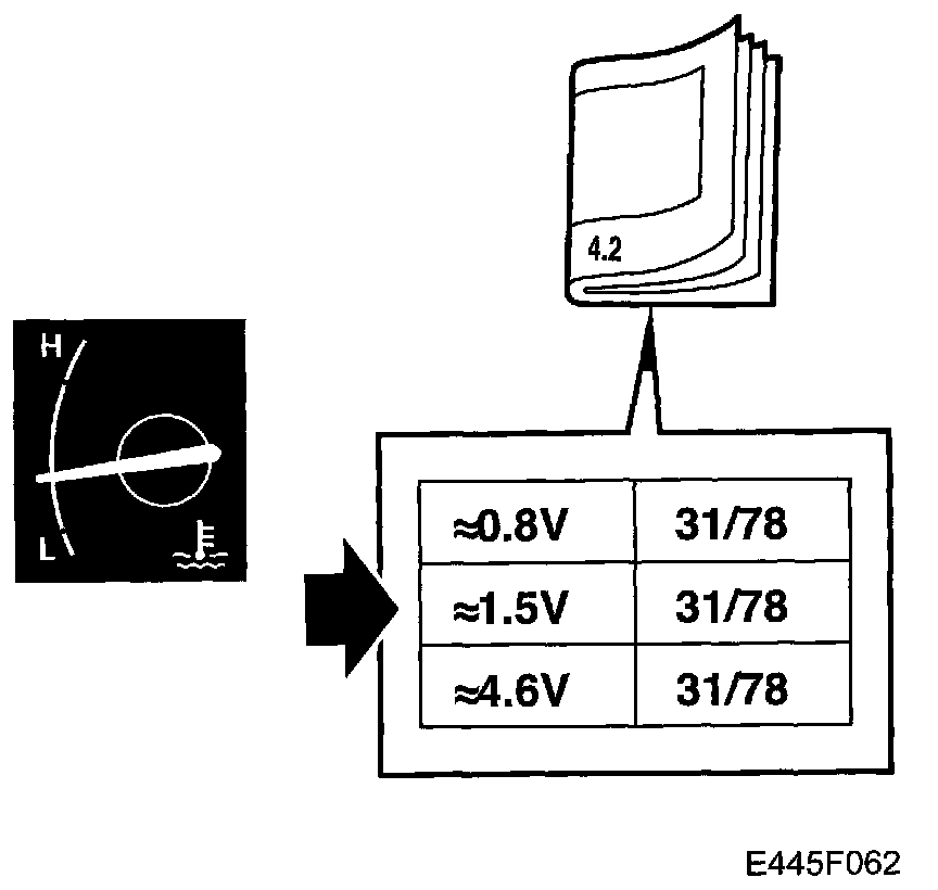
^ The specified test readings refer to those obtained with a calibrated Fluke 88/97.
^ Test readings %(+) and ms(+) indicate the signal's pulse ratio and pulse duration. A test instrument capable of measuring pulse ratio and pulse width must be used. The sign denotes a positive trigger pulse, TRIG+.
Pin 1 - Pin 38:
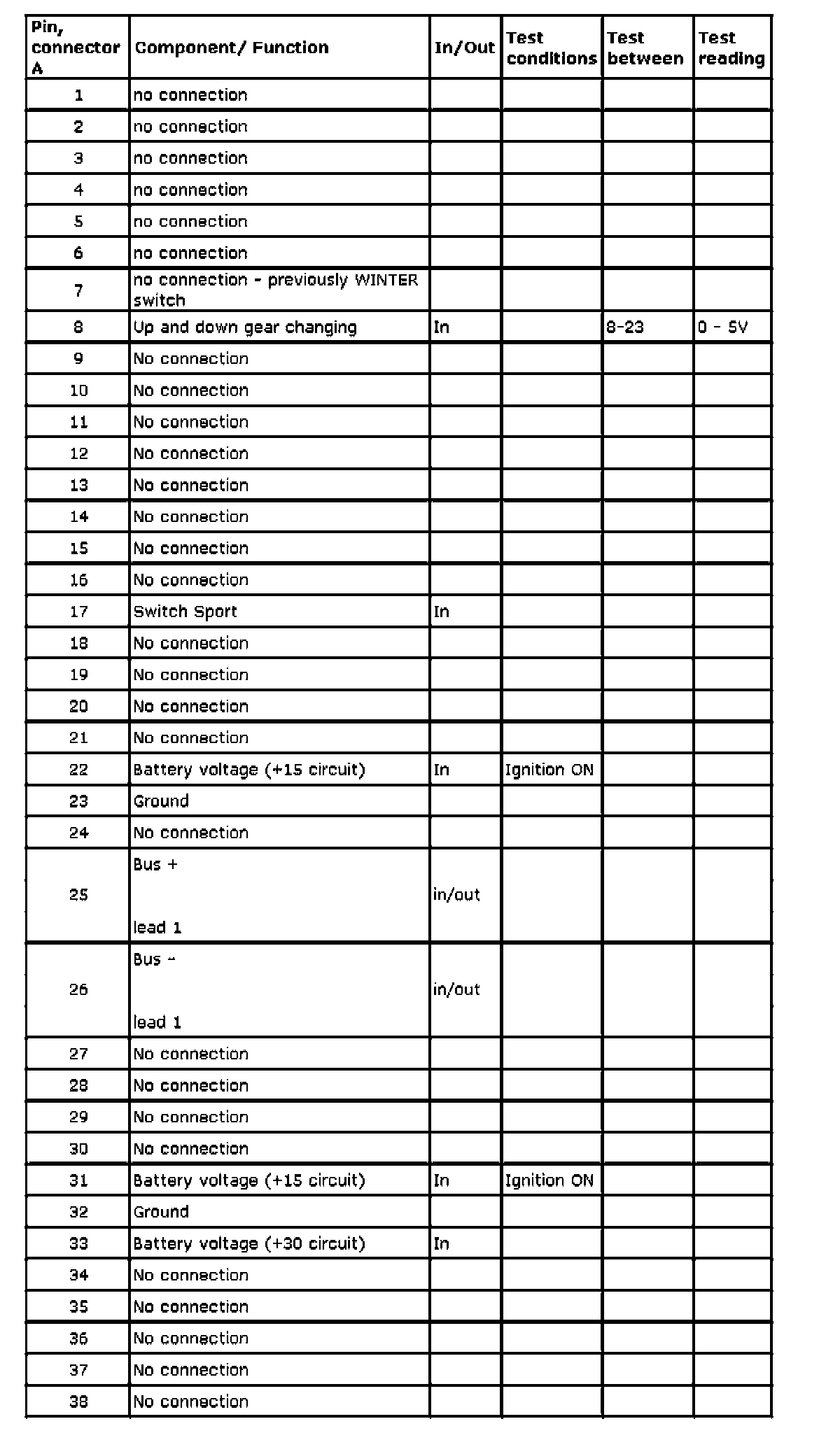
Table connector A
Pin 1 - Pin 21:
Pin 22 - Pin 38:
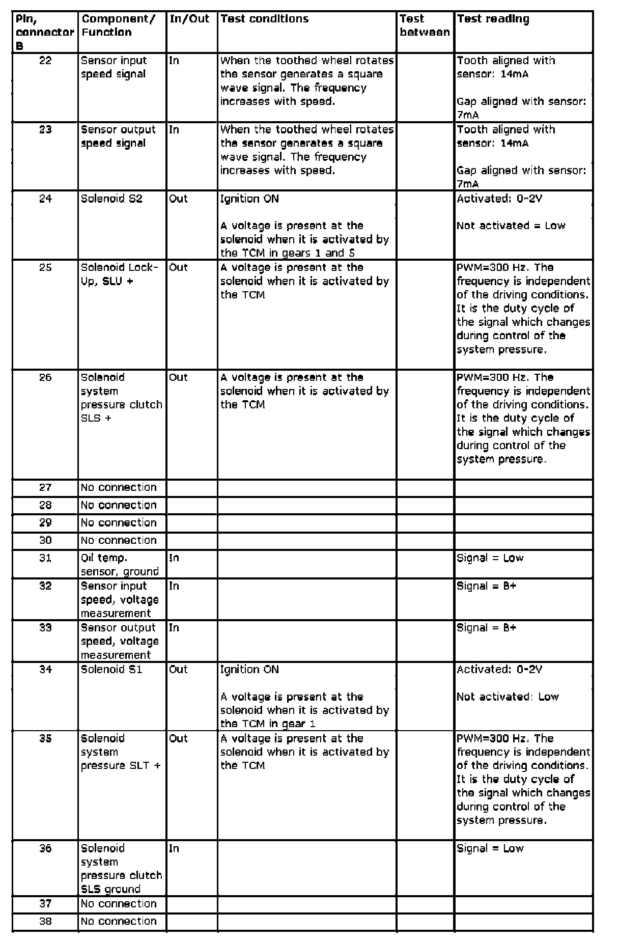
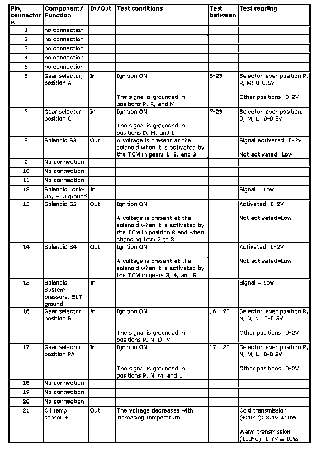
Table connector B