Issued: 2/13/91
Revised
Category
T
Applicable Model/s
1991 626/MX-6
(USA Made)
Subject
"ROOM" FUSE BLOWS
DESCRIPTION
On some vehicles, the interior (room) and map lamps may not come on. Also, on models with A/T, the driver may not be able to move shift lever from "P" position while depressing brake pedal. Check for a blown 15-amp "room" fuse # 16. A blown "room" fuse may be caused by a pinched wiring harness at the left "A" pillar.
NOTE:
1. If the room fuse is blown or missing, this will also effect ECU memory, foot and ignition key lamps, trunk lamp, clock, power antenna, burglar alarm and audio system functions.
2. The shift lever can he moved using "Manual Override Switch."
VIN OF PRODUCTION CHANGE
1YVGD****M5106677 August 20, 1990
INSPECTION PROCEDURE
1. Turn ignition switch off. Make sure interior and map lamps are turned off.
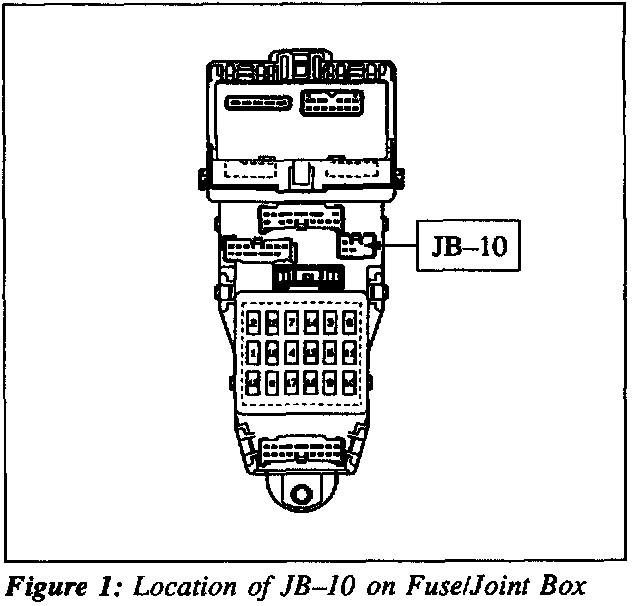
2. Disconnect the JB-10 (3-wire) connector from the fuse/joint box (at left kick panel). Figure 1.
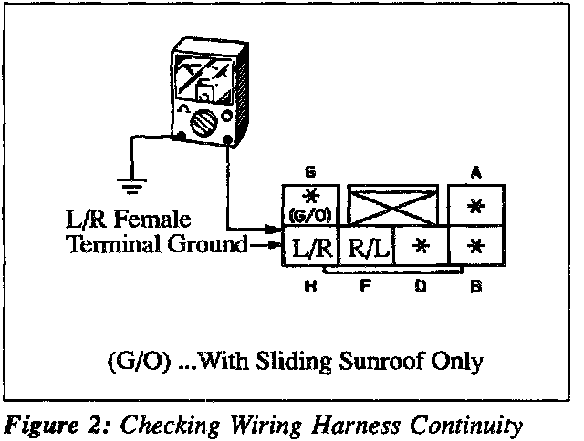
3. Using an ohmmeter, check resistance between terminal H (Blue/Red wire) and ground. If open circuit (no continuity) is present, wiring harness is not the problem. Figure 2.
4. If short circuit (continuity) is present, proceed with repair procedure.
REPAIR PROCEDURE
1. Remove cover and screw at upper left corner of front trim panel. Carefully pull off left "A" pillar trim panel.
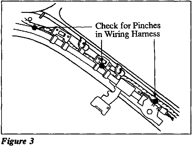
2. Check wiring harness, behind passive shoulder belt rail, for evidence of being pinched. If so, remove passive shoulder belt rail. Repair the wiring harness as necessary. Figure 3.
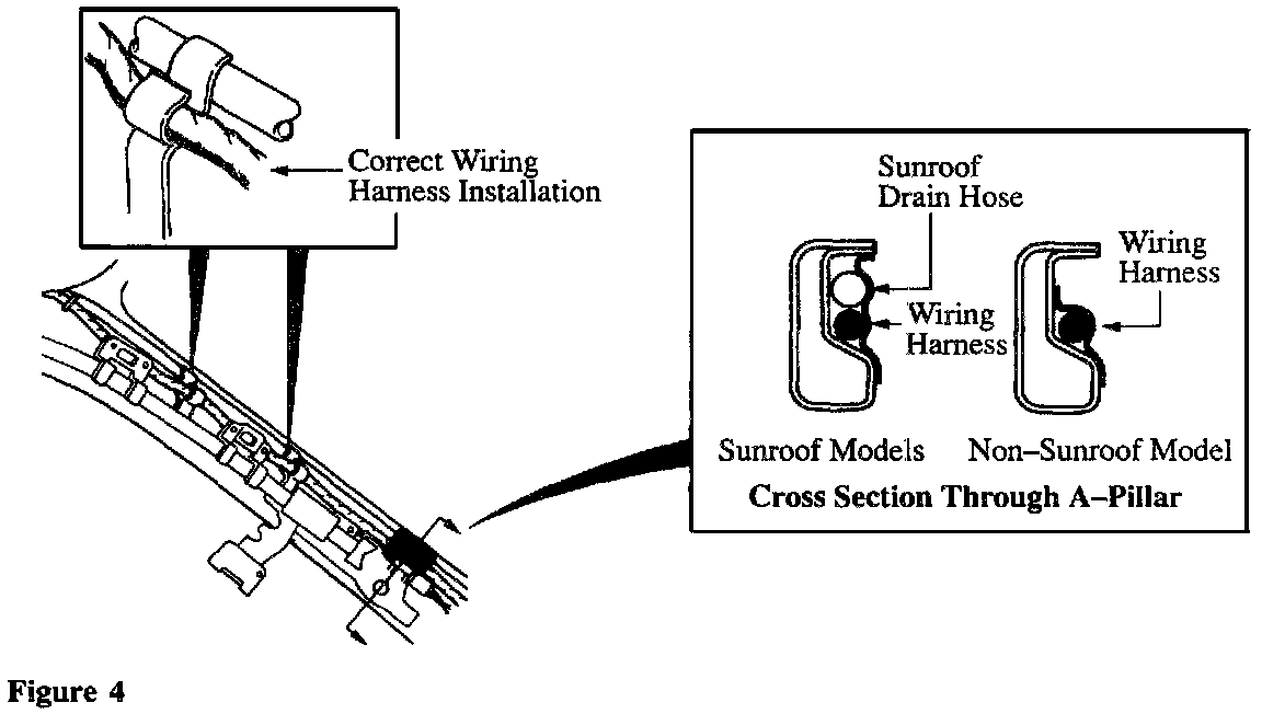
3. Ensure wiring harness is positioned in plastic clips at "A" pillar. Place wiring harness in "A" pillar groove (away from mounting bolt hole) and secure with tape. Ensure mounting bolt hole is not covered. Figure 4.
4. Install passive shoulder belt rail and trim panel. Check wiring harness as previously described to make sure circuit is now open. Reconnect JB-10 connector to fuse/joint box. Install a new fuse.
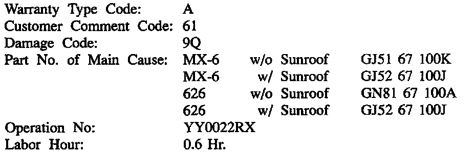
WARRANTY INFORMATION