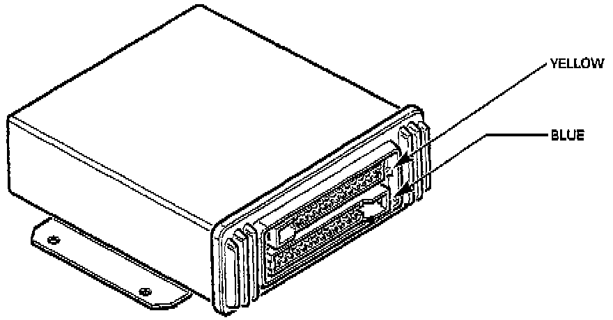
The ECM contains two double sided printed circuit boards. One is a low power board and the other is a high power board. The YELLOW and BLUE 25-way connectors are therefore referred to as the low and high power connectors respectively. Most of the input signals from engine mounted sensors, and interfaces with other systems are located on the low power (Yellow) connector. The high power connector (Blue), mainly serves outputs such as fuel injector drive and relay activation. Inputs and outputs are included with the wiring diagrams.
The ECM receives sensor inputs and feedbacks, which are used to determine the optimum strategy for the prevailing conditions. The ECM's strategy has 256 memory locations containing injector pulse durations and ignition timing angles for 16 different engine loads (engine load sites) and 16 different engine speeds (engine speed sites). Canister purge, idle speed, air injection and exhaust gas recirculation are controlled by the ECM from stored strategies.
Engine Control Module: